Description and Specification for Lab Tenders
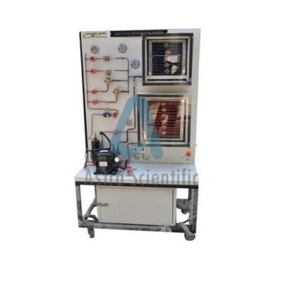
Refrigeration Cycle and Heat Pump System, We are manufacturer, supplier, exporter and solution provider in quality Refrigeration Cycle and Heat Pump System.
Refrigeration Cycle and Heat Pump System is designed to learn the theory
of Heat Transfer in refrigeration engineering. With proper setup,
KR-115 can be emulated as a Refrigeration or Heat Pump system. All
system components are mounted on the front panel so that students are
able to directly watch, touch the components,
and hear the noise produced by the components while it is running under
either Refrigeration or Heat Pump cycle.
KR-115 offers three expansion devices available for the
refrigerant to pass through; they are pressure expansion valve,
capillary tube, and thermal expansion valve. Students can use the
control panel to switch the preferred expanding path from three
expansion devices and compare the corresponding performance under
Refrigeration or Heat Pump cycle.
The state of the refrigerant can be clearly observed through 6
sight glasses at different phases of the Refrigeration / Heat Pump
cycle. 5 hand valves are used to manually control the flowing direction
of the
refrigerant circulating through the system. Student must use the valves
to lead the refrigerant to the appropriate flowing direction so that
the system can operate in corresponding cooling / heating condition. If
students mislead the refrigerant to wrong flowing direction, the
pressure protection switches will detect the conflict and halt the
compressor to prevent the system being damaged. 1. Refrigeration
circulation system with capillary tube
2. Refrigeration circulation system with pressure expansion control
valve
3. Refrigeration circulation system with thermal expansion control
valve
4. Reverse cycle heat pump system
5. Reverse cycle heat pump system without refrigerant receiver
6. Drawing Mollier Chart
7. Calculating system performance
8. Comparison of system performance
9. Comparison of energy between cooling and heating experiments
10. Coefficient of performance (COP) and energy efficiency ratio (EER)-
All system components, including condenser, compressor, evaporator,
capillary tube, filter, refrigerant
receiver, accumulator, hand valves, pressure gauges, expansion
devices, are mounted on the front
panel for direct operation and observation
- Use control panel to select heat pump cycle (cooling or heating), fan
speed of evaporator and
condenser, and expanding path of the refrigerant
- Use control box to monitor the system voltage and current as well as
heat pump status.
- Provide three types of expansion devices, including capillary tube,
pressure expansion valve, and
thermal expansion valve for refrigerant to pass through.
- Provide 6 sight glasses to observe the refrigerant status before and
after passing evaporator,
condenser, expansion devices, and compressor.
- Provide 5 hand valves to control the flowing direction of the
refrigerant.
- Provide high and low pressure protection switches to automatically
halt the compressor when
detecting wrong refrigerant flowing path.
- The refrigerant path for high pressure tube is painted in red and for
low pressure tube is painted in blue.

